A quick guide to shape and position tolerance symbols
An overview of common shape and position tolerance symbols and their significance for precise production and the correct fit of components.
The nature of technical drawing in CNC machining: A comprehensive guide for modern manufacturers
In the rapidly evolving world of manufacturing, the importance of clear communication between designers, engineers and manufacturers cannot be overstated. One of the cornerstones of this communication is the technical drawing. In this article, we take an in-depth look at the intricacies of the technical drawing, its importance to CNC machining and the best practices for creating it, complete with illustrative examples.
The undeniable importance of the technical drawing
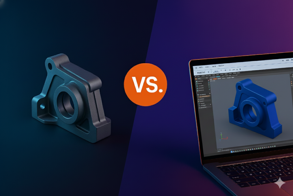
Technical drawings may seem traditional, but they are the backbone of modern manufacturing processes. They serve as a bridge that ensures that the vision of the designer or engineer is accurately translated into the end product by the manufacturer.
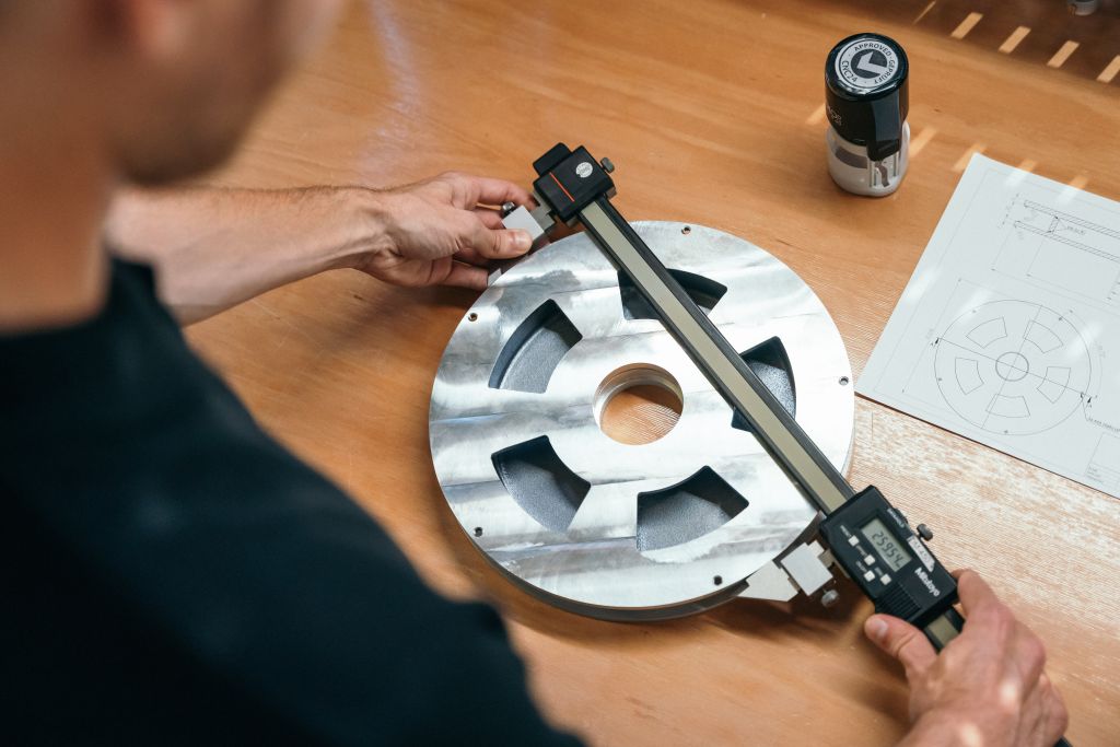
Take, for example, a complex component such as a gear wheel. While a 3D CAD model shows the overall shape and size, a technical drawing shows the number of teeth, their pitch and other production-relevant dimensions that are required for manufacture and functionality.
The anatomy of an effective technical drawing
A well-crafted technical drawing is a mixture of art and science. It usually consists of:
Title block: This section contains important details about the part, such as the name, material specifications, designer’s credentials and more. For example, a title block for a stainless steel screw could include the grade of steel used, tensile strength and other relevant data.
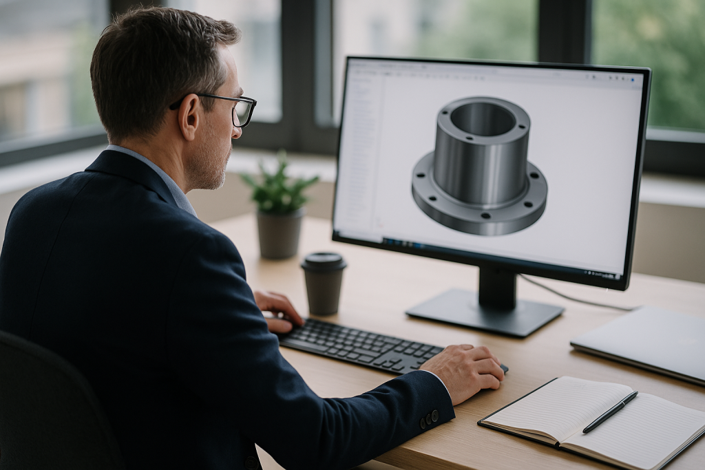
Isometric view: This view offers a three-dimensional perspective and provides a holistic picture of the part, making the drawing immediately understandable. Imagine a complex assembly like a piston-cylinder assembly; an isometric view would show how these parts fit together in three dimensions.
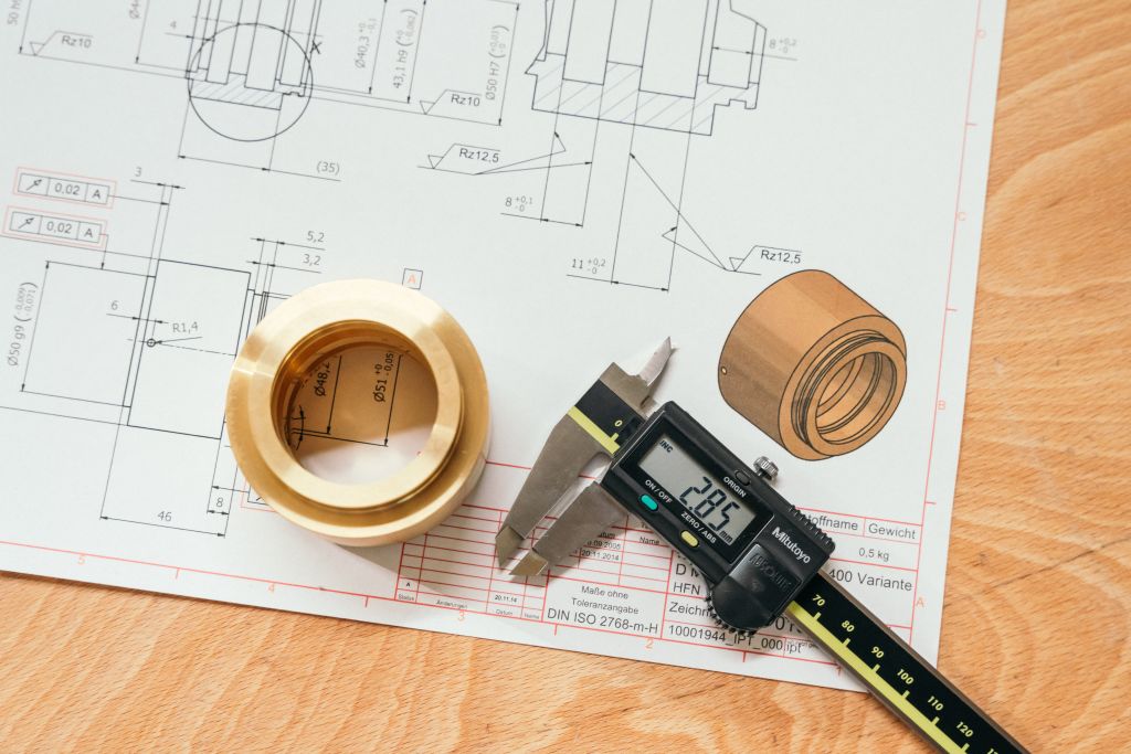
Orthographic views: These are two-dimensional representations that show the exact shape and dimensions of the part from different angles. For a component such as a flange, orthographic views would show the shape from above, from the side and from the front, detailing features such as bolt holes and their spacing.
Sectional views: Particularly useful for parts with internal features, sectional views show the cross-sectional details of a component. Think of a hollow shaft with internal grooves; a sectional view would show these grooves and their dimensions.
Notes for the manufacturer: These are important notes that contain additional information or specific instructions that may not be included in the main drawing. For example, a note may contain a surface finish requirement such as “Ra 0.8 µm”.
Get a quote for your parts
Tolerances: The unsung heroes of precision manufacturing
In the field of CNC machining, precision is the be-all and end-all. Tolerances play a crucial role when it comes to ensuring that the end product meets the specifications exactly. They define the permissible limit deviations for a specific dimension and ensure that the component functions optimally, especially if it has to interact with other components.
Shape and position tolerances are used to define and communicate technical tolerances. Below you will find a brief guide to some common symbols:
Flatness (⏥): Ensures that a surface is uniformly flat. It does not require a reference point and is applied directly to surfaces.
Straightness (⏤): Ensures that a feature is straight in 2D. Often used for linear features such as bars or rails.
Roundness (◯): Ensures that a feature is round in 2D. Often used for cylinders or pins.
Cylindrical shape (⌭): Combines straightness, circularity and taper. Used for cylindrical features.
Perpendicularity (⊥): Ensures that a feature is exactly 90 degrees to a reference point. Usually used for components that must fit flush with another.
Inclination (∠): Ensures a certain angle between two features.
Parallelism (∥): Ensures that two features are parallel to each other.
Position (⌖): Determines the center point of a feature and ensures that it is positioned correctly.
Coaxiality/concentricity (◎): Ensures that the center axis of a feature coincides with another feature.
Symmetry (⌯): Ensures that a feature is symmetrical to a reference plane.
Understanding these symbols is crucial for accurate manufacturing and ensuring that components fit and function as intended. Comprehensive information can always be found in the standards on shape and position tolerances.
| Specification | Features | Icon | Required date |
| Flatness | Uniformity of a surface | ⏥ | No |
| Straightness | Linearity of a feature in 2D | ⏤ | No |
| Roundness | Roundness of a circular feature | ◯ | No |
| Cylinder shape | Combines straightness, circularity and taper | ⌭ | No |
| Perpendicularity | 90-degree orientation of two features | ⊥ | Yes |
| Inclination | Specific angular orientation of two features | ∠ | Yes |
| Parallelism | Parallel orientation of two features | ∥ | Yes |
| Position | Determines the center point of a feature | ⌖ | Yes |
| Coaxiality/ Concentricity | Central axis alignment of two or more features | ◎ | Yes |
| Symmetry | Symmetrical alignment of a feature around a reference plane | ⌯ | Yes |
CNC24’s promise of unparalleled top performance
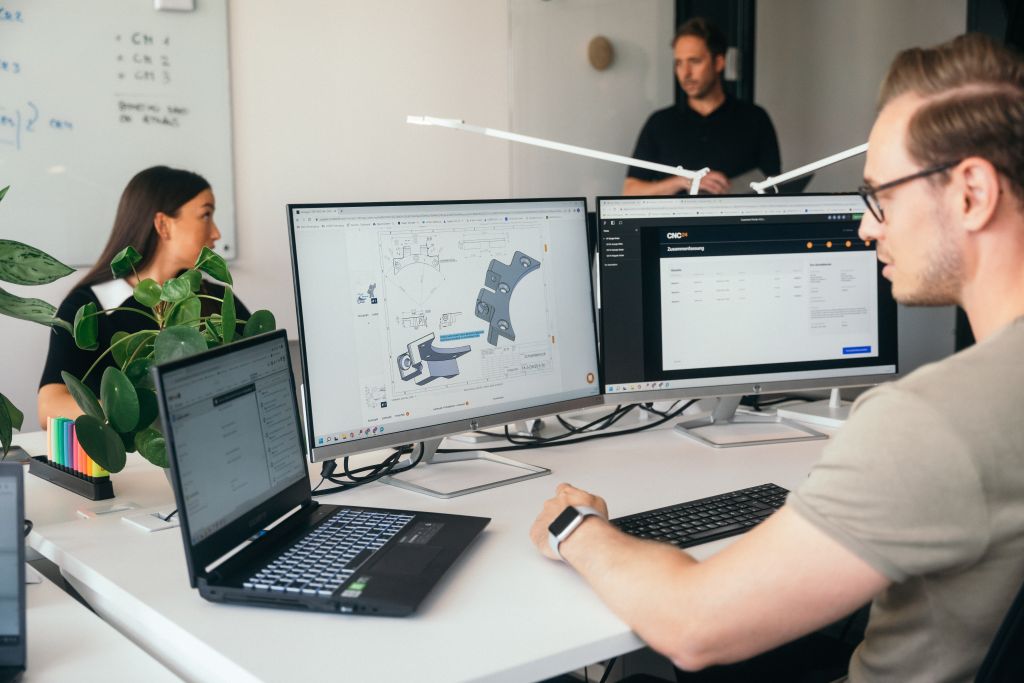
At CNC24, we pride ourselves on our in-depth understanding of CNC machining. Our experienced team of professionals excel at understanding technical drawings and ensuring that every part we produce seamlessly matches the designer’s vision.
For example, if a technical drawing specifies a certain thread type for a screw, our team ensures that the thread is produced exactly according to the specifications, be it a metric thread or a special thread.
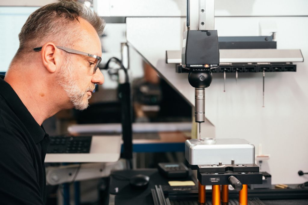
In addition, every component that we manufacture for our customers is precisely measured in our measuring center in Berlin. This stringent quality control is reflected in our remarkably low complaint rate of < 0.017%. This unwavering commitment to precision, quality and excellence has cemented our reputation as a reliable, long-term partner for all CNC machining projects.
Conclusion
In the dynamic world of CNC machining, the technical drawing has proven to be an indispensable tool. It ensures that the intricate details of a component are communicated effectively and paves the way for successful production.
At CNC24, we are at the forefront of this synergy between design and manufacturing, ensuring that every project is a testament to precision and quality. For example, if a customer requires a bespoke gear with a specific module and pressure angle, our team ensures that these parameters are met with the utmost precision, resulting in a gear that fits perfectly into its counterpart.
Optimization of your supplier search
Download Whitepaper
Find out now which 9 points you should consider so that you can find the right supplier and reduce your costs by up to 40%.
Please note that the whitepaper is only available in the German language.
Related Posts
-
 Resources, CNC, Sheet Metal Processing, Manufacturing
Drawing parts: A specialty in CNC machining
Discover how CNC24 optimizes CNC machining and promotes innovation through the integration of drawing parts.
-
 CNC
CNCCNC machining in medical technology: precision and versatility from CNC24
CNC machining in medical technology enables the production of high-precision and reliable components such as surgical instruments, orthopaedic implants and prostheses. Find out more about the versatile applications and advantages of this manufacturing technology.
-
 Procurement, Manufacturing
Quality assurance in CNC manufacturing: The Ultimate Guide for Procurement Managers
Quality assurance is the key to successful CNC procurement: procurement managers are faced with the challenge of reconciling costs, delivery times and increasing quality requirements. This practical guide shows how quality assurance and quality control interact, which standards and test procedures are relevant and how key performance indicators such as Cpk, PPM or OTD can be used correctly. With checklists, tables and best practices, the article provides a comprehensive overview for an efficient and secure supply chain.
-
 Procurement
The ultimate procurement platform for components: How CNC24 is revolutionizing industrial parts procurement
In times of increasing complexity in supply chains and rising cost pressure, one topic is coming more into focus: indirect procurement. Also known as indirect procurement, it encompasses all those procurement processes that do not flow directly into the end product but tie up considerable resources. In technical purchasing in particular, this proportion can be greater than expected - especially in CNC parts procurement.
-
 Blog
BlogCNC machining online: Upload file, receive quotation, have component manufactured
Procuring CNC components has never been so easy: with digital manufacturing platforms such as CNC24, you can upload your CAD file, receive a binding quote in no time at all and have your parts manufactured to the highest quality standards - without the need for a lengthy search for suppliers. In this article, we show you how the process works, what you should look out for and what advantages CNC machining online offers for buyers and designers.